ESP32 Pulse-Width Modulation (PWM)
MOHAMMAD SAIFIQUL AIMAN B MOHAMMAD ALI
192011145
1) First, you need to choose a PWM channel. There are 16 channels from 0 to 15.
2) Then, you need to set the PWM signal frequency. For an LED, a frequency of 5000 Hz is fine to use.
3) You also need to set the signal’s duty cycle resolution: you have resolutions from 1 to 16 bits. We’ll use 8-bit resolution, which means you can control the LED brightness using a value from 0 to 255.
4) Next, you need to specify to which GPIO or GPIOs the signal will appear upon. function accepts two arguments. The first is the GPIO that will output the signal, and second is the channel that will generate the signal.
5) Finally, to control the LED brightness need to use PWM.
Here’s a list of parts you need to assemble the circuit
ESP32 DOIT DEVKIT V1 Board
5mm LED
330 Ohm resistor
Breadboard
Jumper wires
ledcAttachPin(GPIO, channel)
This function accepts two arguments. The first is the GPIO that will output the signal, and the second is the channel that will generate the signal.
ledcWrite(channel, dutycycle)
This function accepts as arguments the channel that is generating the PWM signal, and the duty cycle.
Assemble the circuit shown below
// the number of the LED pin
const int ledPin = 16; // 16 corresponds to GPIO16
// setting PWM properties
const int freq = 5000;
const int ledChannel = 0;
const int resolution = 8;
void setup(){
// configure LED PWM functionalitites
ledcSetup(ledChannel, freq, resolution);
// attach the channel to the GPIO to be controlled
ledcAttachPin(ledPin, ledChannel);
}
void loop(){
// increase the LED brightness
for(int dutyCycle = 0; dutyCycle <= 255; dutyCycle++){
// changing the LED brightness with PWM
ledcWrite(ledChannel, dutyCycle);
delay(15);
}
// decrease the LED brightness
for(int dutyCycle = 255; dutyCycle >= 0; dutyCycle--){
// changing the LED brightness with PWM
ledcWrite(ledChannel, dutyCycle);
delay(15);
}
}
Uploading the Sketch :
Before clicking the upload button, go to Tools Board, and select the board you’re using. In my case. It’s the DOIT ESP32 DEVKIT V1 board. Also don’t forget to select your ESP32’s COM port.
Now, press the upload button.
Then, wait for the “Done uploading.” message:
Testing your project :
Getting the Same Signal on Different GPIOs
Different GPIOs can provide the same signal from the same channel. To do this, simply connect those GPIOs to the same setup channel ().
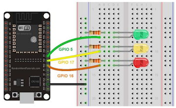
Let's extend the previous example by dimming three LEDs with the same PWM signal coming from the same channel.
Assemble the circuit shown below
Source code :
// the number of the LED pin
const int ledPin = 16; // 16 corresponds to GPIO16
const int ledPin2 = 17; // 17 corresponds to GPIO17
const int ledPin3 = 5; // 5 corresponds to GPIO5
// setting PWM properties
const int freq = 5000;
const int ledChannel = 0;
const int resolution = 8;
void setup(){
// configure LED PWM functionalitites
ledcSetup(ledChannel, freq, resolution);
// attach the channel to the GPIO to be controlled
ledcAttachPin(ledPin, ledChannel);
ledcAttachPin(ledPin2, ledChannel);
ledcAttachPin(ledPin3, ledChannel);
}
void loop(){
// increase the LED brightness
for(int dutyCycle = 0; dutyCycle <= 255; dutyCycle++){
// changing the LED brightness with PWM
ledcWrite(ledChannel, dutyCycle);
delay(15);
}
// decrease the LED brightness
for(int dutyCycle = 255; dutyCycle >= 0; dutyCycle--){
// changing the LED brightness with PWM
ledcWrite(ledChannel, dutyCycle);
delay(15);
}
}
Uploading the Sketch :
Before clicking the upload button, go to Tools Board, and select the board you’re using. In my case. It’s the DOIT ESP32 DEVKIT V1 board. Also don’t forget to select your ESP32’s COM port.
Now, press the upload button.
Then, wait for the “Done uploading.” message:
Testing your project :


Comments
Post a Comment